Brushless and closed-loop spindle control describe different parts of a system. Brushless identifies a motor’s commutation method. Closed-loop speed control describes feedback used to compare the running speed with a requested speed and correct the difference. A motor can be brushless without that label establishing closed-loop RPM regulation, and a brushed motor can also have speed feedback.
PWM adds a third distinction. It describes pulse-width modulation, which may appear at a command interface or inside a drive’s power electronics. When comparing a CNC spindle motor, read those three claims separately: how the motor turns, how a speed is requested, and what the system actually regulates.
Commutation keeps the motor turning
Commutation means switching current through motor windings in the appropriate sequence. In a brushed DC motor, brushes and a mechanical commutator perform that switching. In a brushless DC motor, electronics perform the commutation. Monolithic Power Systems explains this construction distinction in its comparison of the two motor types.
Removing brushes removes that particular wearing contact. It does not remove bearings or make the complete spindle maintenance-free. More importantly for a buyer reading speed-control claims, electronic commutation is not itself a statement about RPM regulation.
A BLDC drive needs information about rotor position to decide when to switch the windings. Hall sensors can provide that information, while other designs estimate position from electrical behavior. The presence of rotor-position information explains how the phases can be switched at the appropriate time; a separate question is whether the controller uses speed feedback to correct a speed error. Renesas distinguishes these functions in its motor-control guidance.
This BLDC explanation should not be applied indiscriminately to every spindle with no brushes. An AC induction spindle and its variable-frequency drive use a different motor architecture. Establish the actual motor type from the configuration’s documentation rather than assigning it from the shape of the housing.
A speed command is different from speed feedback
PWM changes the proportion of time a pulsed signal is on, called its duty cycle. In a motor power stage, switching can vary the effective voltage applied to the windings. At a CNC controller’s interface, a PWM signal may instead communicate a speed request to another device. The same term can therefore describe signals at different points in the system.
That distinction matters when reading “PWM spindle control.” It can describe how the CNC sends a request without saying how the drive responds to changes in load. It also does not establish a universal input voltage, frequency or connector. The command interface has to match the exact paired equipment; it is not interchangeable merely because two descriptions both contain “PWM.”
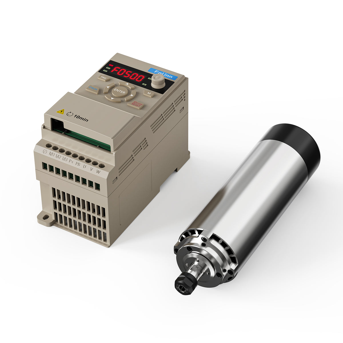
Nor does a number on a screen settle the feedback question. CNC software may show the speed it requested. Depending on the drive and selected display mode, a panel can show a frequency, setpoint, parameter or feedback value. The pictured panel is a hardware illustration, not a measurement of shaft RPM. Its display meaning comes from the corresponding manual.
Closed-loop speed control adds a comparison: the running speed, measured or estimated by the documented system, is compared with the reference. The controller then changes its output in response to the difference. Microchip’s AN885 describes speed-error correction and explains how Hall transitions or an encoder can provide speed information. Merely having a Hall sensor does not establish that this speed-regulating function is implemented.
“Sensorless” needs the same care. A drive can estimate motor behavior from electrical signals instead of using a separate physical position sensor. The absence of an external encoder does not, on its own, prove the absence of a speed-regulation loop. Ask what feedback or estimation the documented operating mode uses and what it controls.
Follow a changing cut through the control system
Consider a hypothetical desktop CNC router carving wood. The operator requests the same spindle speed for a light pass and a pass with greater cutter engagement. The motor can continue commutating correctly in both passes while its actual speed responds differently to the load.
If the arrangement supplies only a fixed command without speed-error correction, that command does not guarantee the same running RPM. If a speed-regulating loop is operating, it can respond to a difference between reference and feedback. This is the distinction the buyer needs to establish; the example is not a test of a particular spindle or evidence of a particular amount of speed change.
The regulating system still has finite current, power and cooling capacity, together with a permitted speed range. A correction request cannot create unlimited torque. Closed-loop speed control is therefore a defined control function, rather than a guarantee of constant RPM under every cut or a promise of a particular surface finish.
Other loops can be present without answering the same question. An axis-position loop concerns the position of the moving axis. A current loop regulates current. A spindle-speed loop concerns rotational speed. A listing that calls the CNC machine “closed loop” needs to identify the relevant quantity before that phrase can answer a spindle-speed question.
Brushes do not rule out feedback, either. Texas Instruments’ sensored-motor application brief includes a brushed-DC example that uses a Hall speed signal to close a speed-control loop. Thus “brushed versus brushless” and “open-loop versus closed-loop speed control” are different comparisons, not two ways of naming the same alternatives.
Compare documented configurations rather than isolated labels
Imagine two hypothetical offers. One lists a brushless motor and a PWM input. That tells the buyer something about construction and the command interface, but does not yet describe regulated RPM. Another explicitly identifies speed feedback, a speed-regulation mode and its operating conditions. Those details answer the control question more directly. They still need to apply to the exact motor and drive supplied, rather than an optional drive mode or another version of the package.
A complete hardware package makes the boundary between components visible. The TwoTrees 1000W air-cooled spindle and drive kit is an example with a separate drive and model-specific package options. Neither its product name nor the photographs establish a particular BLDC architecture, feedback method or closed-loop speed mode. Those are separate specifications to establish for the actual configuration being considered.
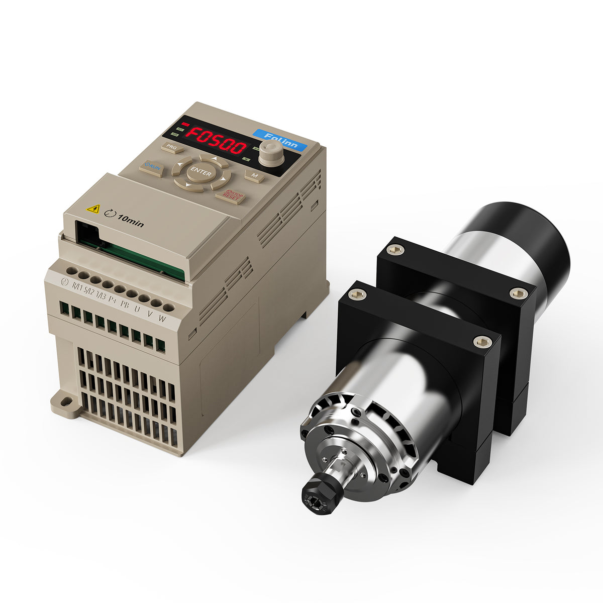
Keep the buyer’s questions specific: which motor architecture is supplied, what interface requests speed, which quantity the selected mode regulates, and what feedback or estimation supports that regulation? Then read the stated operating limits. A controller’s ability to send a request, a drive’s ability to commutate a motor and a system’s ability to regulate speed are related functions, but none can stand in for documentation of the others.
This interpretation is a purchasing and specification task. It is not a basis for rewiring a drive, adding sensors, changing control gains or bypassing protective provisions. Installation and adjustment must follow the exact equipment instructions and appropriate qualified support. Once the three claims are separated, “brushless,” “PWM” and “closed loop” can describe a coherent system without implying more than the configuration actually specifies.